Topography Tools
Right clicking on the node the “Topography” option, a window will appear with the available tools (Figure 248).
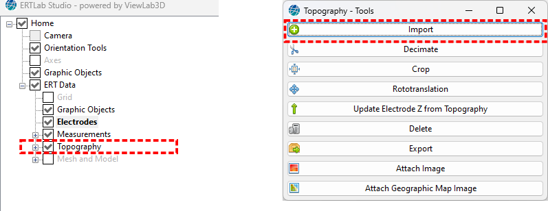
Figure 248 Topography tools panel
Import
To import a topography, load a .txt file with 3 columns, one for each coordinate (X, Y, Z) (Figure 249). Each row of the topography file corresponds to one topographic point.
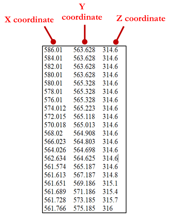
Figure 249 Example of Topographic file
If the loaded file is composed by a high number of points, with excessive spatial definition not needed for the ERT work purpose, ERTLab Studio automatically suggests a decimation of it (Figure 250).
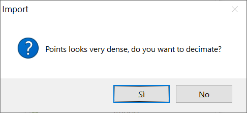
Figure 250 Automatic decimation of Topography file
It is also possible to do this later through the dedicated tool (see Decimate).
Decimate
If the topography file is too big and slowing-down the application, the file can be decimated through this option.
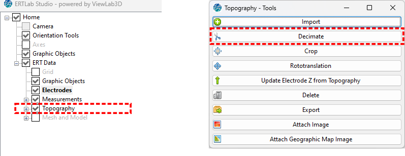
Figure 251 Topography tools panel
Clicking on the Decimate button will open a window (Figure 252).
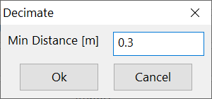
Figure 252 Decimate radius
Topographic points located at a distance smaller than indicated in the Min Distance box are deleted. Be careful not too delete to many points to not decimate the file too much to not lose the topography resolution.
Crop
If the topography data points extent too much beyond the ERT area of interest the topography can be cropped with this option.
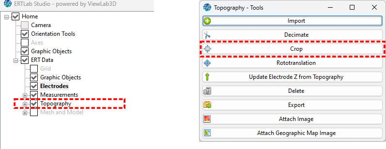
Figure 253 Crop tool
Figure 254 shows a big topography surface with an ERT line in loop configuration in a small area.
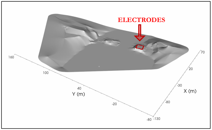
Figure 254 Example of extended topography
Using the Crop button allows to cut it typing the proper coordinates in the number boxes (Figure 256).
To find the maximum and minimum crop values use the Picker tool (see section View Picker settings).
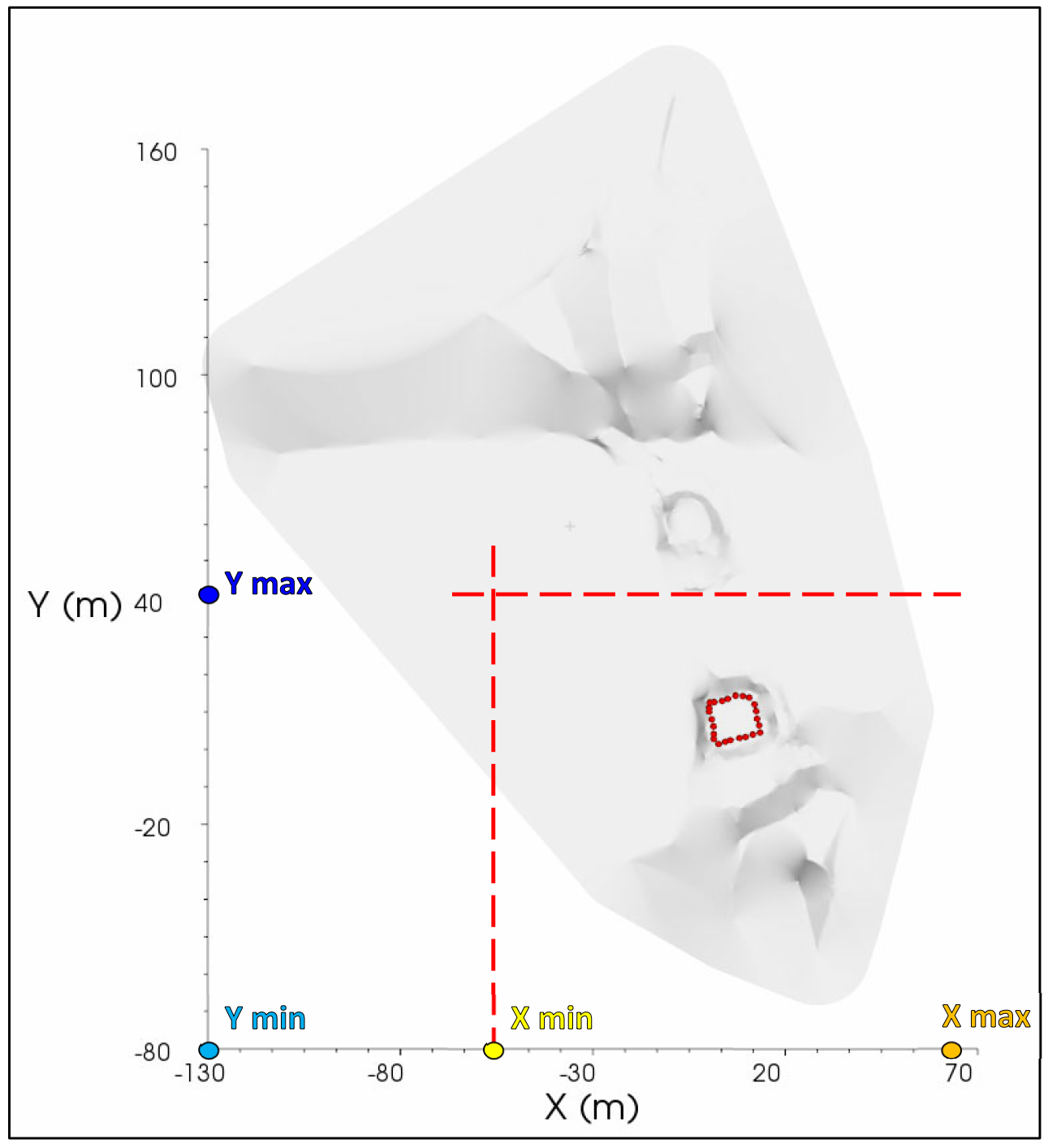
Figure 255 Choice of cut values to focus on the area of interest
Checking the keep inside box (Figure 256), all the points of the topography which are outside the selected limits are deleted.
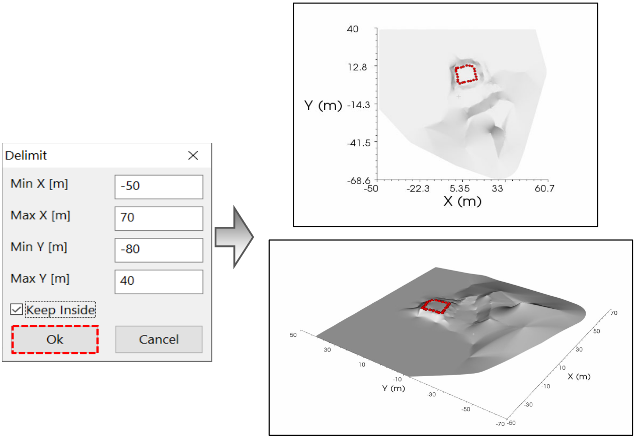
Figure 256 Result of topography crop
Rototranslation
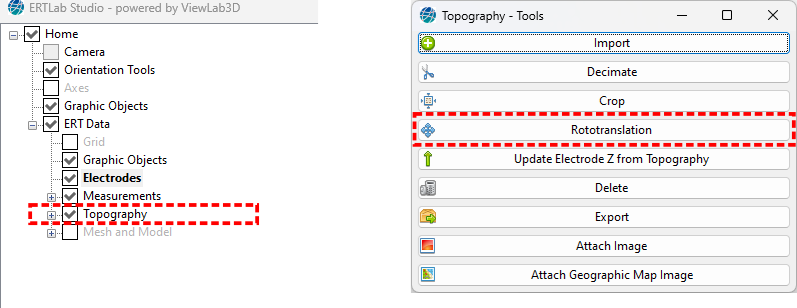
Figure 257 Rototranslation tool
This option allows the translation and rotation of the Topography in the 3D dimensions (see section Rototranslation). It performs a real rototranslation and not only a graphic one, so when exporting the coordinates in a .txt files after having applied a rototranslation they are different from those imported.
Update Electrodes Z from topography
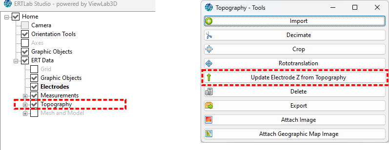
Figure 258 Update Z tool
When a Topography is loaded, it can happen that one or more electrodes are not coincident with the Z coordinate of the topography. They can appear elevated or buried. With this option the Z of the electrodes can be updated to match the topography. In the following example, some elevated electrodes are on the topographic Z surface after the application of this option.
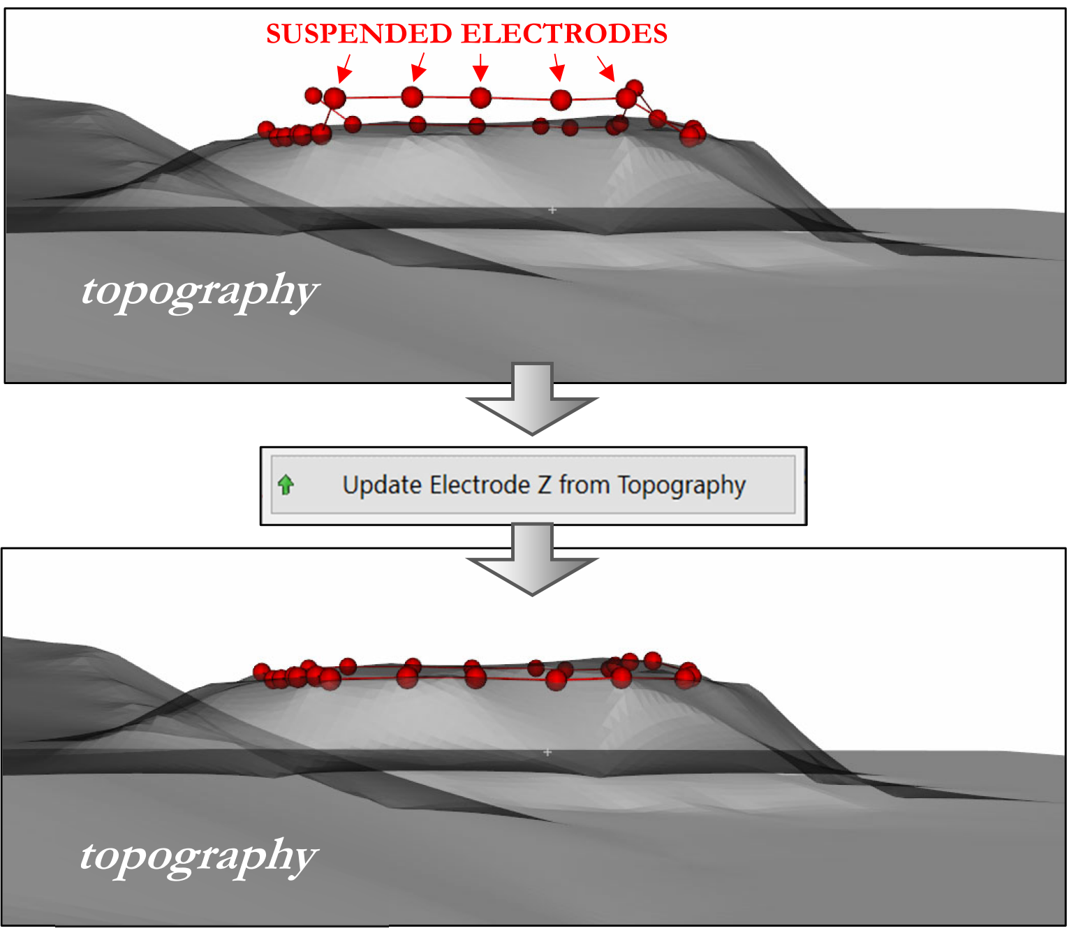
Figure 259 Example of Z electrode update from Topography
Delete
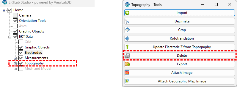
Figure 260 Delete tool
Clicking on the Delete button deletes all the points of the topography and there is no longer any topographic information.
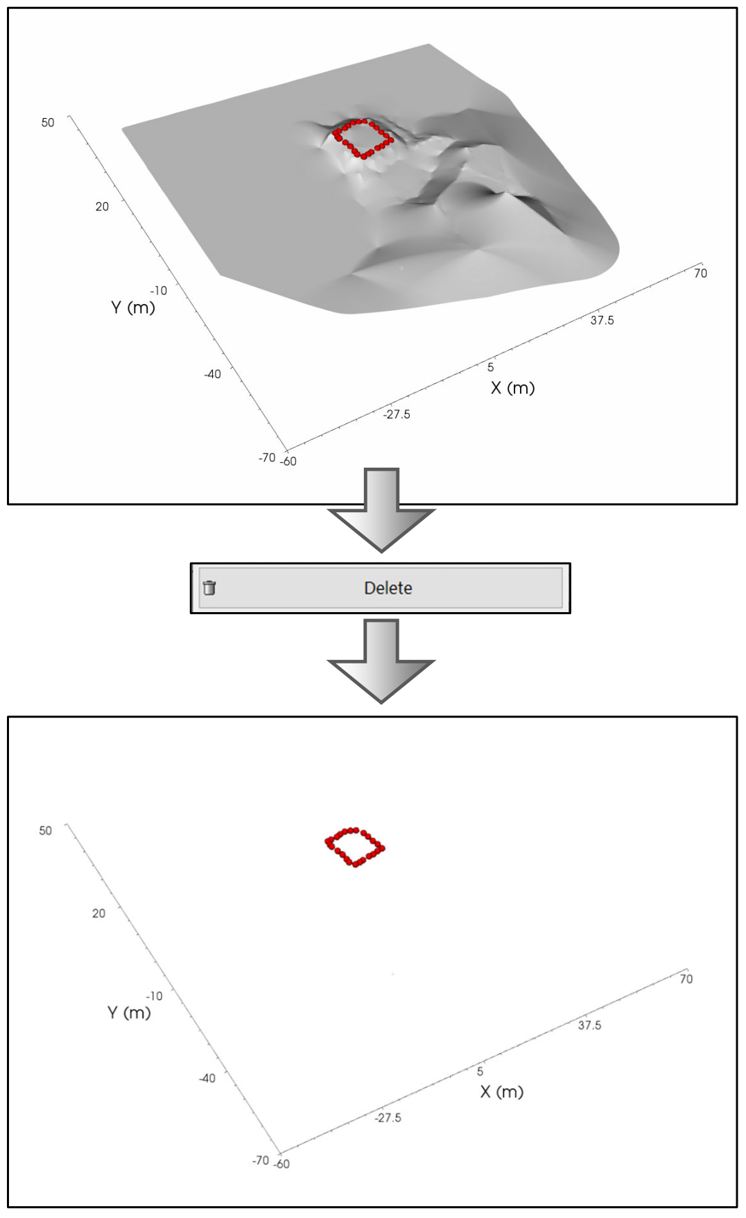
Figure 261 Example of delete Topography
Export
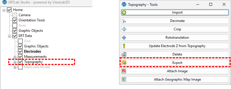
Figure 262 Export tool
Clicking on the Export button all the points of the topography can be saved to a text file.
Attach Image
Warning
Feature not enabled in the default license type
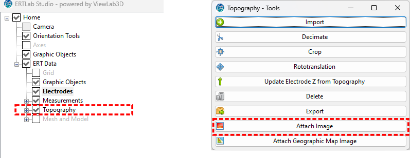
Figure 263 Image tool
By default the topography surface has an homogeneous colour, in some cases can be useful to paint that surface with some image. After that the image is selected a new child node in the tree is created, there the image can be customized (see Image).
Note that by default the size of the image is 1m by 1m, placed at the centre of the scene, so it is often needed to edit it.
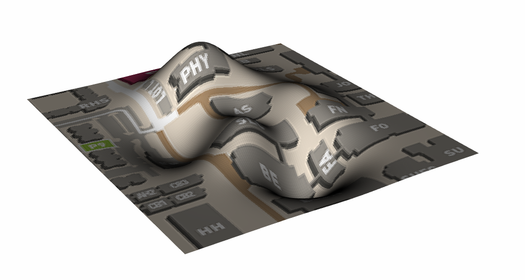
Figure 264 Example of Image on Topography
Attach Geographic Map Image
Warning
Feature not enabled in the default license type
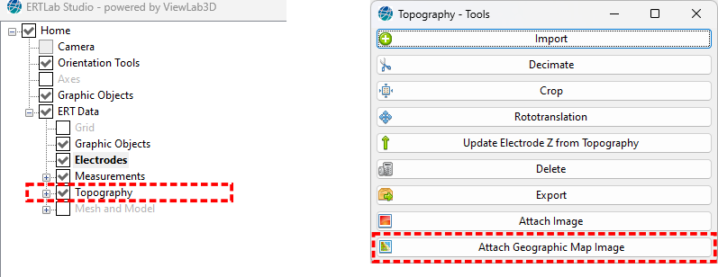
Figure 265 Geographic Map tool
By default the topography surface has an homogeneous colour, in some cases can be useful to paint that surface with some map. A new child node in the tree is created, there the map can be customized (see Geographic Map Image).
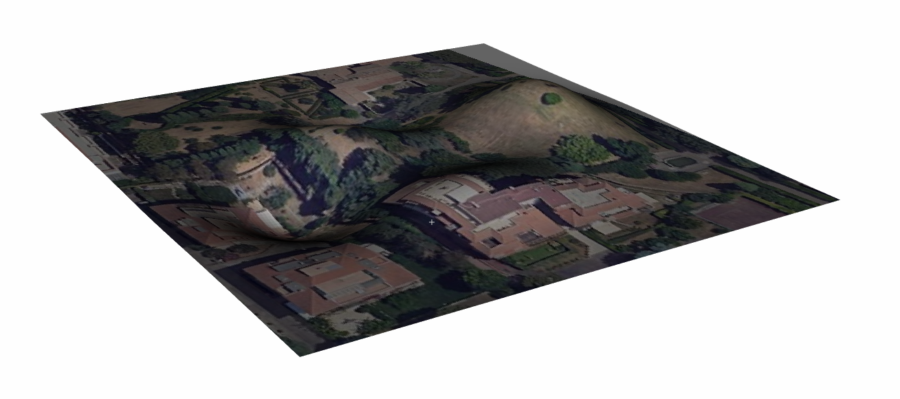
Figure 266 Example of Geographic Image on Topography