Camera
This menu item (Figure 18) allows to operate on the 3D scene and to modify the visualization mode through some tools with the following functionality
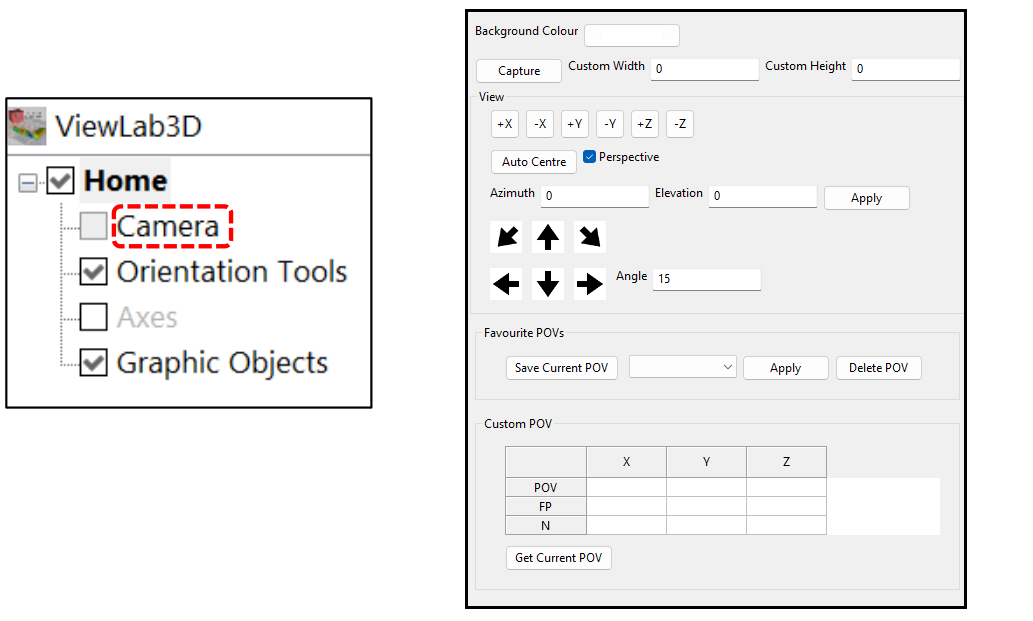
Figure 18 Camera panel
Background Colour
The background colour can be selected, which is white by default. As an example, in Figure 19 it is set to a grey and an orange background colour.
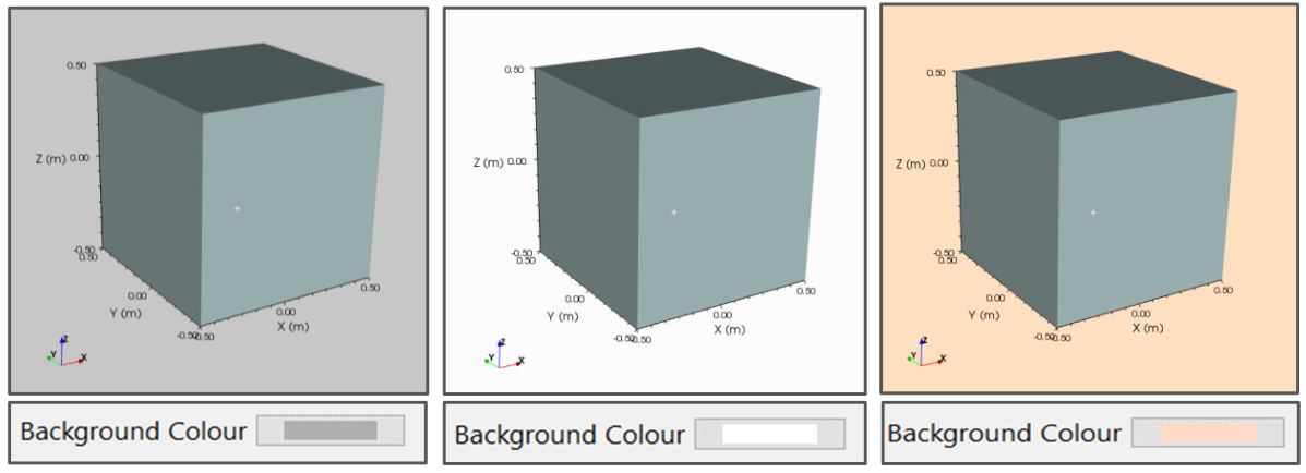
Figure 19 Different choices of background colour
Capture
Allows to save what is currently shown in the 3D scene as an image file; the same button is in the 3D scene, on the top of the 3D panel (Figure 20).
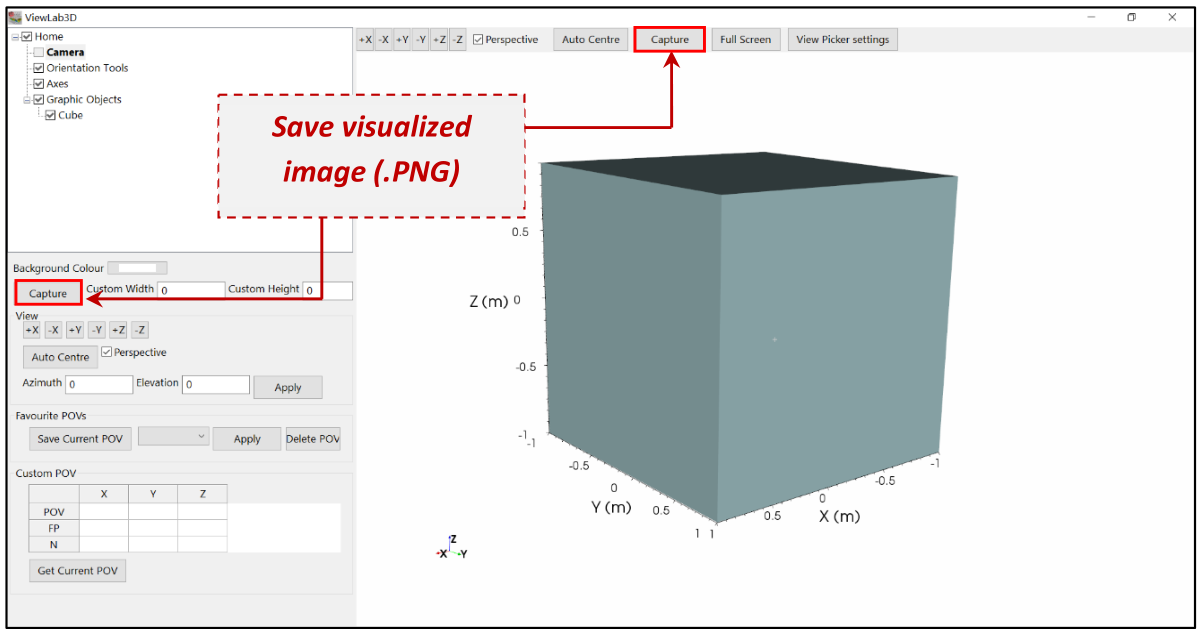
Figure 20 Capture tool to save the current image
It is possible to save the scene in most common raster image formats like PNG, JPEG, TIFF, BMP.
If the view is set from the top and the prospective is disabled, then it will be saved in the same folder of the image file a world file (see for example Wikipedia ), that is a location reference of the image and can be used from GIS software to correctly locate the image (see for example GeoTIFF file format ).
It is also available some experimental exports to 3D file format (see VRML and X3D). You can check our free viewer to share these files with your clients.
http://www.geostudiastier.com/ViewLab3D/OnlineViewer
It is possible to choose the width and the height (in pixels) of the image to save. Figure 21 shows what is obtained inserting, e.g. 1000 pixels as width value and 2000 pixels as height value, and vice versa.
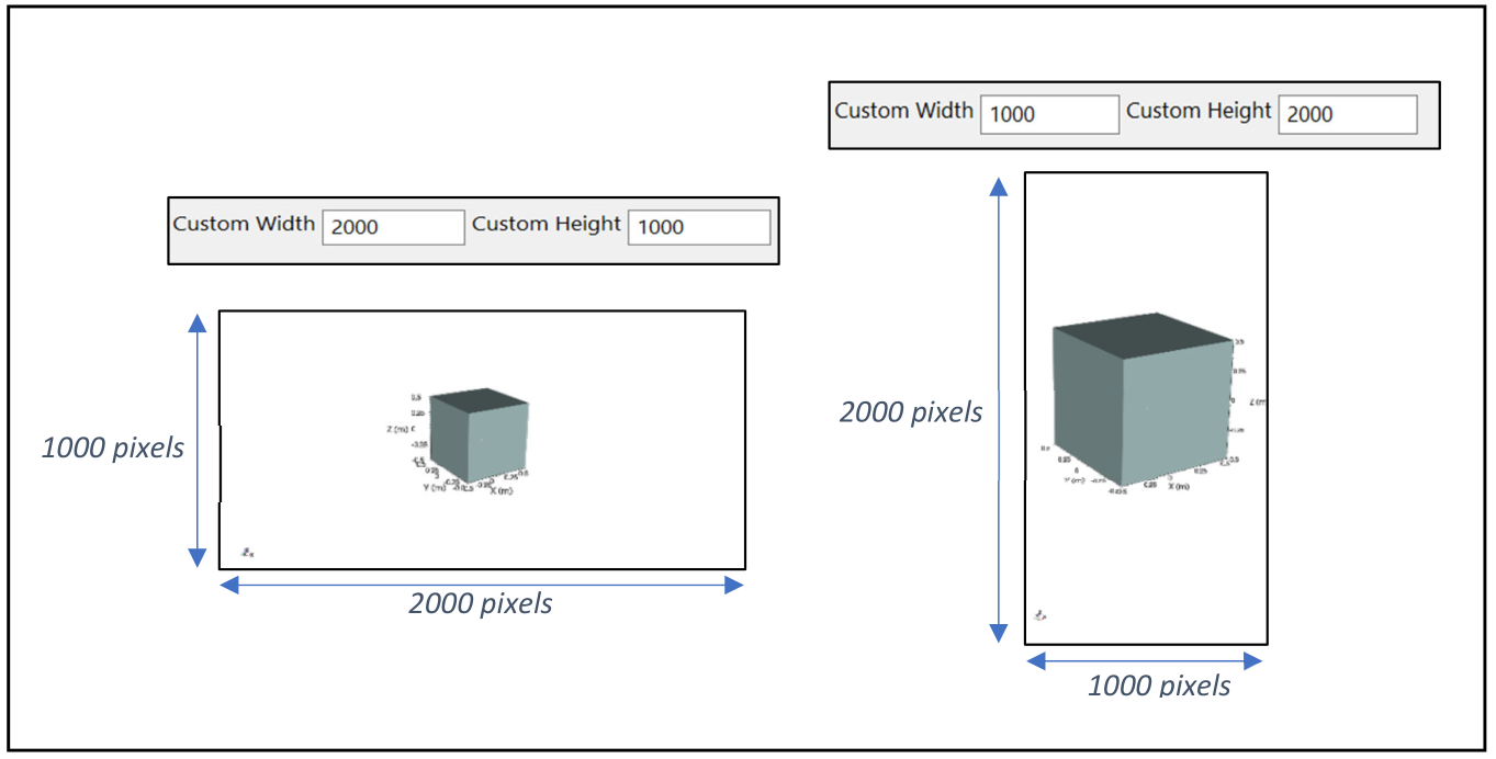
Figure 21 Different choices of width and height values
Please note that common image resolution can be like:
4:3 |
16:9 |
|
|---|---|---|
VGA 360p |
480 x 360 |
640 x 360 |
SD 480p |
640 x 480 |
854 x 480 |
HDready 720p |
960 x 720 |
1280 x 720 |
FullHD 1080p |
1440 x 1080 |
1920 x 1080 |
QuadHD / 2K 1440p |
2560 x 1440 |
|
UltraHD / 4K 2160p |
3860 x 2160 |
|
8K |
7680 x 4320 |
|
16K |
15360 x 8640 |
XYZ buttons
Allow the user to rotate the scene along one of the three axes (X, Y, Z) and to specify from which direction (“-” and “+”) to observe it. As an example, three objects (a cube, a sphere and a pyramid) are observed from different points of view as shown in Figure 22.
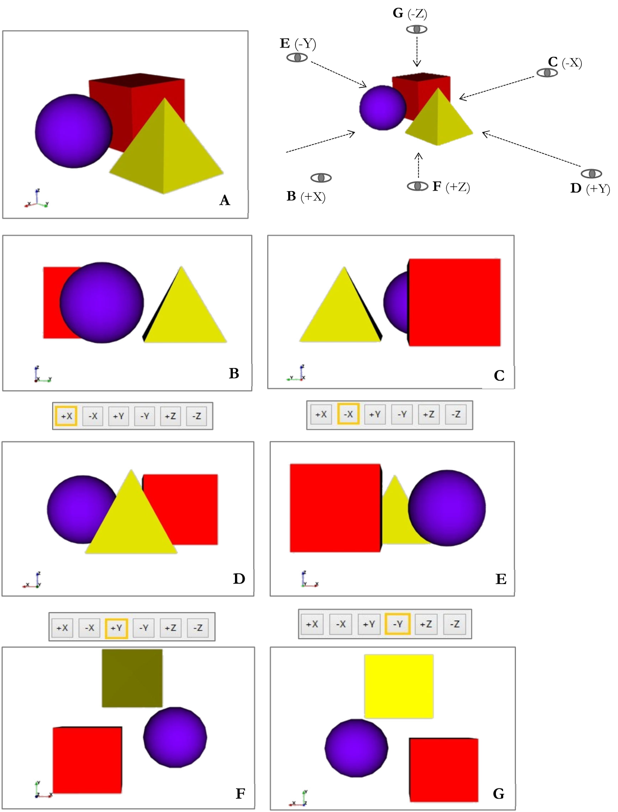
Figure 22 Different points of view of objects along one of the 3 axes
In A view from a casual point of view, in B view from positive X axis (+X), in C view from negative X axis (-X), in D view from positive Y axis (+Y), in E view from negative Y axis (-Y), in F view from positive Z axis (+Z) and in G view from negative Z axis (-Z)
Auto Centre
Sets automatically the object at the centre of the scene, as shown in Figure 23.
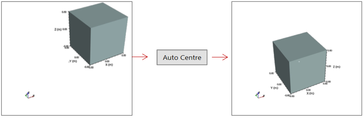
Figure 23 In A the object is in a general position, in B it is at the centre of the scene after the application of Auto Centre tool
Perspective
Switches from a perspective view to an orthogonal view (Figure 24). The red dashed lines helps to appreciate the difference between the two approaches to visualize the same object.
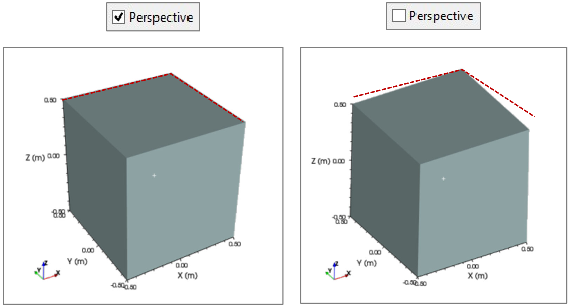
Figure 24 In A prospective view, in B orthogonal view
Azimuth and Elevation
They are an alternative to placing the object in the scene through the direct action of the mouse. It is possible to set specific values of azimuth and elevation. Starting from the point of view “+Y” (Figure 25 A), the value of the Azimuth determines the angle of rotation in horizontal, so around the Z axis (simulating a view of the object from the right with positive values, Figure 25 B and from the left with negative values, Figure 25 C). The Elevation value determines the angle of the vertical rotation, around the X axis (simulating a view for the top with positive values, Figure 25 D and from the bottom with negative values, Figure 25 E). Figure 25 F shows an example in which both values are different from zero (+35° for Azimuth and Elevation). In order to better appreciate the direction of the displacement of the cube, the logo of the software has been inserted in the face of the cube parallel to XZ plane.
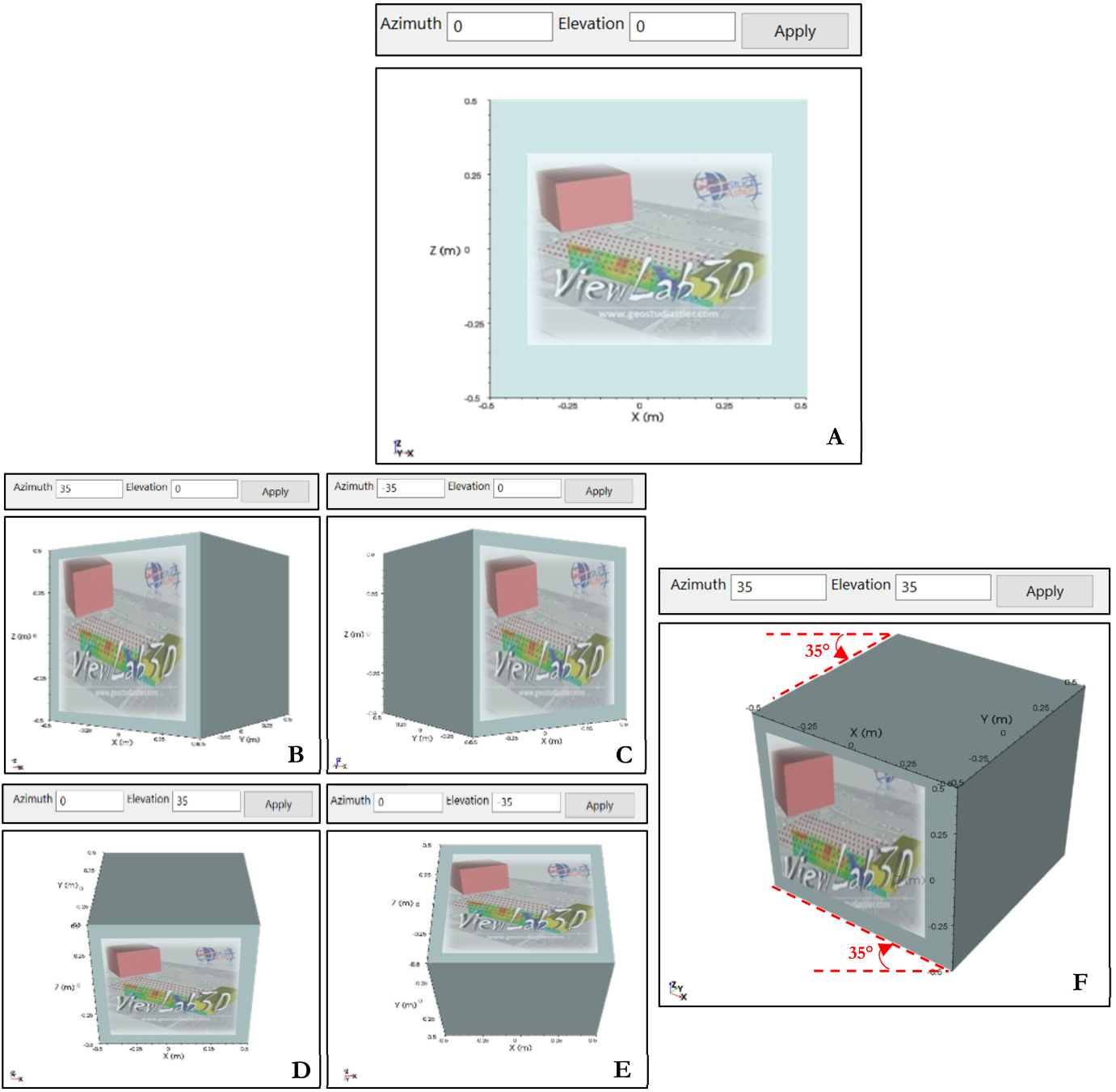
Figure 25 Different cases of Azimuth and Elevation values
To obtain similar results the camera can be moved also using the image buttons shown in Figure 26, discrete camera rotation will be performed at each click. It is also possible to set the Angle value to customize the rotation amount.
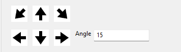
Figure 26 Discrete camera rotation
Favourite POVs
This tool allows to save some specific positions of the object in the 3D scene and to reload it later.
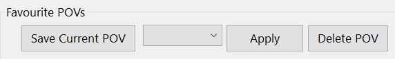
Figure 27 Point of View panel
To save the current view click on the “Save Current Point of View (POV)” button. It is possible to name a POV setting using the proper box (it is empty in the figure) and clicking Apply. Clicking on the “Delete POV” button deletes the selected Point of View.
Custom POV
Allows to set a specific Point Of View by inserting the desired coordinates X, Y, Z of the desired POV (Point Of View), FP (Focal Point), and N (Normal) in the proper table. The “Get Current POV” button updates the table to the values currently used in the 3D scene; it is possible to edit them to set the desired view mode (Figure 28).
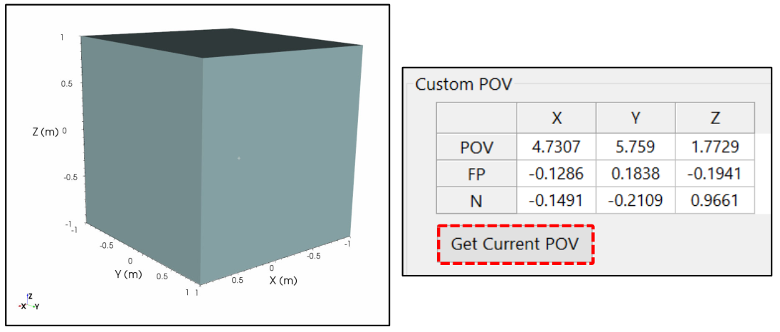
Figure 28 Autofill of table POV-FP-N in function of the position of the cube